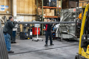
Large diameter tube bending requires careful evaluation of material properties, wall thickness, bend radius, tooling, and dimensional requirements. A design that works well with smaller tubing may present entirely different manufacturing challenges at a larger scale.
For OEM engineers developing exhaust systems, fluid conveyance components, structural assemblies, and other industrial applications, understanding these challenges early can help prevent costly design changes and production delays.
At Morton Industries, tube bending is a core manufacturing capability, with the ability to bend tubing ranging from 1/8 inch to 12 inches in outside diameter. Working across this range requires an understanding of how tube geometry, material behavior, and manufacturing processes interact.
What Is Large Diameter Tube Bending?
Large diameter tube bending is the process of forming larger tubular components into specified angles and radii while controlling deformation and maintaining the dimensional requirements of the finished part.
There is no universally accepted diameter that separates standard tube bending from large diameter tube bending. The distinction often depends on the equipment, tooling, material, and manufacturing application.
Regardless of the exact diameter, larger tubular components introduce considerations involving forming forces, material movement, tooling requirements, and part handling.
For engineers, the challenge is not simply determining whether a tube can be bent. It is determining whether the required geometry can be manufactured consistently while meeting the component’s functional and dimensional requirements.
1. Bend Radius Becomes Increasingly Important
One of the first considerations in large diameter tube bending is the relationship between tube outside diameter and centerline radius (CLR).
Centerline radius is measured from the center of the bend to the centerline of the tube.
Engineers commonly express bend radius as a multiple of the tube’s outside diameter.
For example, a 12-inch OD tube designed with a 2D centerline radius would have a 24-inch CLR.
This relationship matters because the severity of a bend depends on more than its physical radius.
A 24-inch CLR may be relatively generous for a smaller tube but represents a much tighter proportional bend for a 12-inch tube.
As the bend radius becomes tighter relative to the tube diameter, the forming process generally becomes more demanding.
Potential challenges include:
- Increased stretching along the outside of the bend
- Compression and potential wrinkling along the inside
- Changes in the tube’s cross-sectional shape
- Additional tooling and forming requirements
- Greater difficulty maintaining consistent finished dimensions
A larger bend radius may simplify manufacturing, but it must still meet the application’s space, fitment, and performance requirements.
The most effective design balances those requirements with the practical limitations of the manufacturing process.
2. Wall Thickness and Tube Diameter Must Be Evaluated Together
Wall thickness plays a critical role in determining how a tube behaves during bending.
However, wall thickness alone does not provide enough information to evaluate bend feasibility.
Engineers must consider wall thickness relative to the tube’s outside diameter.
A useful measurement is the wall factor:
Wall Factor = Outside Diameter ÷ Wall Thickness
For example, a 12-inch OD tube with a 0.25-inch wall thickness has a wall factor of 48.
This ratio helps describe the relative thinness of the tube wall. Higher wall factors generally indicate greater susceptibility to deformation during bending, although material properties, bend radius, and tooling also influence the result.
Two tubes with identical outside diameters can behave very differently if their wall thicknesses vary.
Similarly, two tubes with the same wall thickness may require different manufacturing approaches when their diameters differ significantly.
For large diameter applications, engineers should evaluate diameter, wall thickness, bend radius, and material together rather than treating them as independent specifications.
3. Controlling Ovality and Cross-Sectional Deformation
One of the challenges associated with tube bending is maintaining the desired cross-sectional shape.
As a round tube bends, its cross-section may become less circular. This deformation is commonly described as ovality.
For certain applications, some ovality may be acceptable. For others, maintaining the internal profile is essential.
Examples include components where dimensional changes could affect:
- Fluid or exhaust flow
- Connection points and sealing surfaces
- Assembly fitment
- Clearance with surrounding components
- Structural or functional performance
Ovality can be expressed as a percentage using the difference between the maximum and minimum measured diameters relative to the original outside diameter.
The allowable amount should be determined by the functional requirements of the component, applicable specifications, and the intended application.
Depending on the geometry and process, specialized tooling and internal support may be used to help control deformation.
For engineers, identifying critical cross-sectional requirements early helps establish appropriate manufacturing and inspection expectations.
4. Material Selection Influences Bend Feasibility
Not all metals respond to bending in the same way.
Material properties such as yield strength, ductility, and work-hardening behavior affect the forces required to form a tube and its tendency to deform or recover after bending.
Carbon steel, stainless steel, aluminum, and other alloys may require different forming approaches even when their dimensions are similar.
For example, materials with higher strength or lower available ductility may present additional challenges when forming tight-radius bends.
Springback is another consideration.
After forming forces are removed, the material may partially recover toward its original shape. The amount of springback depends on the material, geometry, and forming process.
In large diameter tube bending, accounting for this behavior is important when developing tooling and processes capable of producing consistent finished components.
Material selection should therefore consider both the intended performance of the part and the requirements of manufacturing it.
5. Tooling and Part Geometry Affect Manufacturing Complexity
Large diameter tube bending requires more than equipment capable of accommodating the tube’s outside diameter.
The complete part geometry must also be considered.
Bend angles, straight sections, overall part length, and the location of additional features can influence tooling selection and the sequence of manufacturing operations.
For example, a large tubular component containing multiple bends may present challenges involving part positioning, equipment clearance, and material handling.
The location of holes, brackets, fittings, or other features can also influence whether those operations should occur before or after bending.
Engineers should consider several questions during the design process:
- Does the design provide sufficient straight length for gripping and positioning?
- Can the required bend geometry be accommodated by the equipment and tooling?
- Will additional features interfere with bending or subsequent operations?
- Are the specified tolerances necessary for the component’s function?
- Could standardizing bend radii or material dimensions simplify production?
Addressing these questions before a design is finalized can help reduce manufacturing complexity and avoid unnecessary tooling changes.
6. Think Beyond the Bend
For many OEM applications, a large diameter bent tube is only one component of a larger assembly.
Additional operations may include laser cutting, end forming, welding, brazing, finishing, and assembly.
Each operation introduces considerations that can influence the original tube design.
A bend location may affect welding access. A hole or slot may require precise positioning relative to the finished bend. A connection point may depend on maintaining a particular cross-sectional profile.
Designing the tube without considering these downstream operations can create manufacturing challenges later.
An integrated approach allows engineers to evaluate the complete component and how it will move through the manufacturing process.
This can create opportunities to simplify production, reduce handling, and improve consistency without compromising the finished assembly.
7. Why Early Manufacturing Collaboration Matters
One of the most effective ways to address large diameter tube bending challenges is to involve manufacturing expertise before the design is finalized.
Early collaboration allows engineering and manufacturing teams to evaluate bend feasibility, tooling requirements, material selection, tolerances, and secondary operations while design flexibility still exists.
This becomes especially important when working with large diameter components, where tooling investments and design changes can carry significant cost implications.
A manufacturable design is not necessarily the simplest design. It is one that achieves the required performance while supporting a practical, repeatable production process.
By evaluating manufacturing requirements early, OEM engineers can make more informed design decisions and reduce the likelihood of unexpected challenges during production.
Large Diameter Tube Bending at Morton Industries
Morton Industries provides tube bending and fabrication solutions for OEMs across a wide range of industrial markets.
Our tube bending capabilities accommodate outside diameters from 1/8 inch to 12 inches, with bend radii ranging from 1D to large roll applications, depending on the material and part requirements.
Our teams work with a variety of materials, including carbon steel, stainless steel, aluminum, brass, and copper.
Beyond tube bending, Morton Industries offers integrated manufacturing capabilities including laser processing, welding, brazing, end forming, finishing, and assembly.
With engineering support, process validation, and tube measurement technology, we work alongside customers to develop components that meet both design requirements and production needs.
From individual tubular components to complex fabricated assemblies, our focus is on helping OEMs turn challenging designs into reliable manufacturing solutions.
Planning a Large Diameter Tube Bending Project?
Successful large diameter tube bending starts long before the first part reaches production.
Whether you’re developing a new component, evaluating bend feasibility, or looking to improve an existing design, early collaboration can make a meaningful difference.
Morton Industries has the equipment, experience, and integrated manufacturing capabilities to help bring your project to life.
Explore our tube fabrication capabilities or contact our team to discuss your next project.
About Morton Industries
Founded in 1946, Morton Industries provides advanced tube and pipe fabrication, sheet metal fabrication, welding, finishing, assembly, and complete manufacturing solutions for OEMs.
With strategically located manufacturing facilities and decades of experience, Morton Industries helps customers solve complex manufacturing challenges and support production at scale.